CADding: The New Drivetrain
sort
|
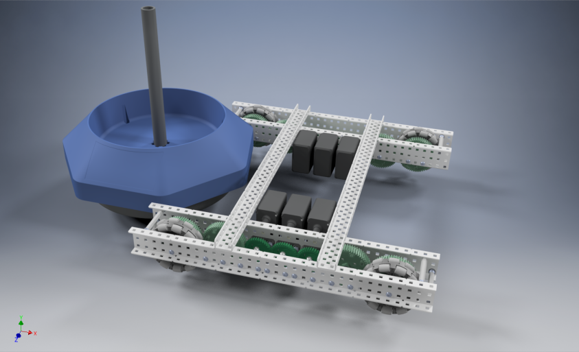
Drivetrain-2.0.0Now that we had all the data about the best drivetrain for our robot we decided we should design it in 3d design software, in line with Design Goal #2 in our Design Brief at the beginning of this notebook. DesignHere is the design that we decided on:
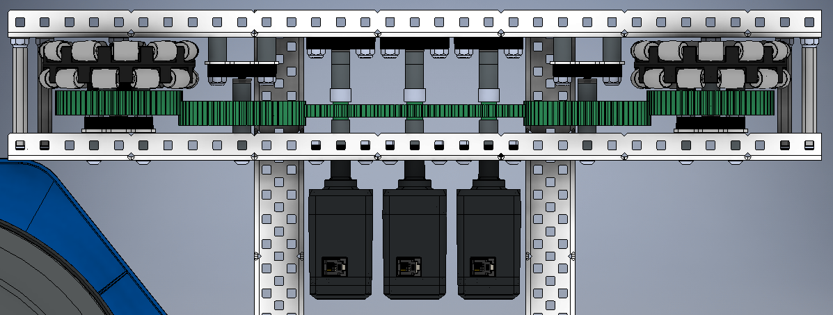
The 1x3x1 c-channels allow the motors to all be mounted right next to each other in a very small amount of room. This is good, because we need to have room for a ring conveyor, an intaking claw, and a Mobile Goal partially within the robot on one side. It will also give us room for tracking wheels. Here is the gear ratio in closer detail in the CAD:
|
-
 The 7 Dorks
the7dorks333A@gmail.com
The 7 Dorks
the7dorks333A@gmail.com
- homeHome
- sortCategories
- labelTags
- personAbout