Field Setup
The field and game elements arrived yesterday, so today, we got ready for the season by:
- Taking apart our Change Up field.
- Setting up our Tipping Point Field.
- Organizing our toolboxes, because they got pretty messy by the end of last season.
Starting Lift-1.0
Once that was all done, we started building the robot based on the CAD.
The intakes were intentionally left unfinished in the CAD, because we could not know exactly how the rings were going to behave in real life, and what type of intakes would be most effective. The CAD tells us how much room we have to build the intakes so as not to interfere with the lift or drivetrain. However, as we build the intakes, we may realize that the drivetrain needs to be redesigned, which would be very time consuming if we already built the drivetrain, so we thought we should start building the intakes first. The intakes also need something to attach to for testing, so decided to build most of the lift as well.
We built:
- Most of the left and right sides of the lift:
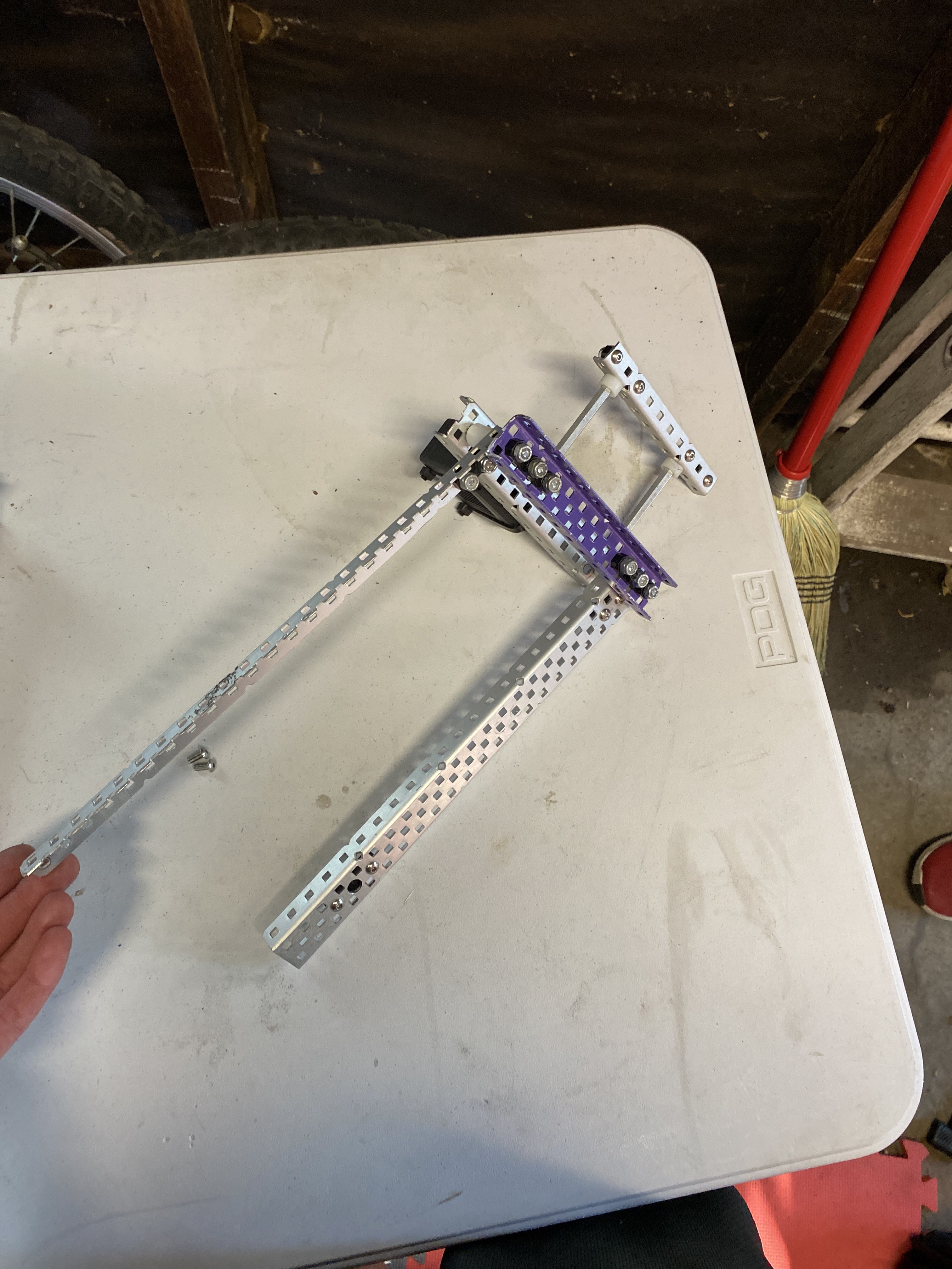
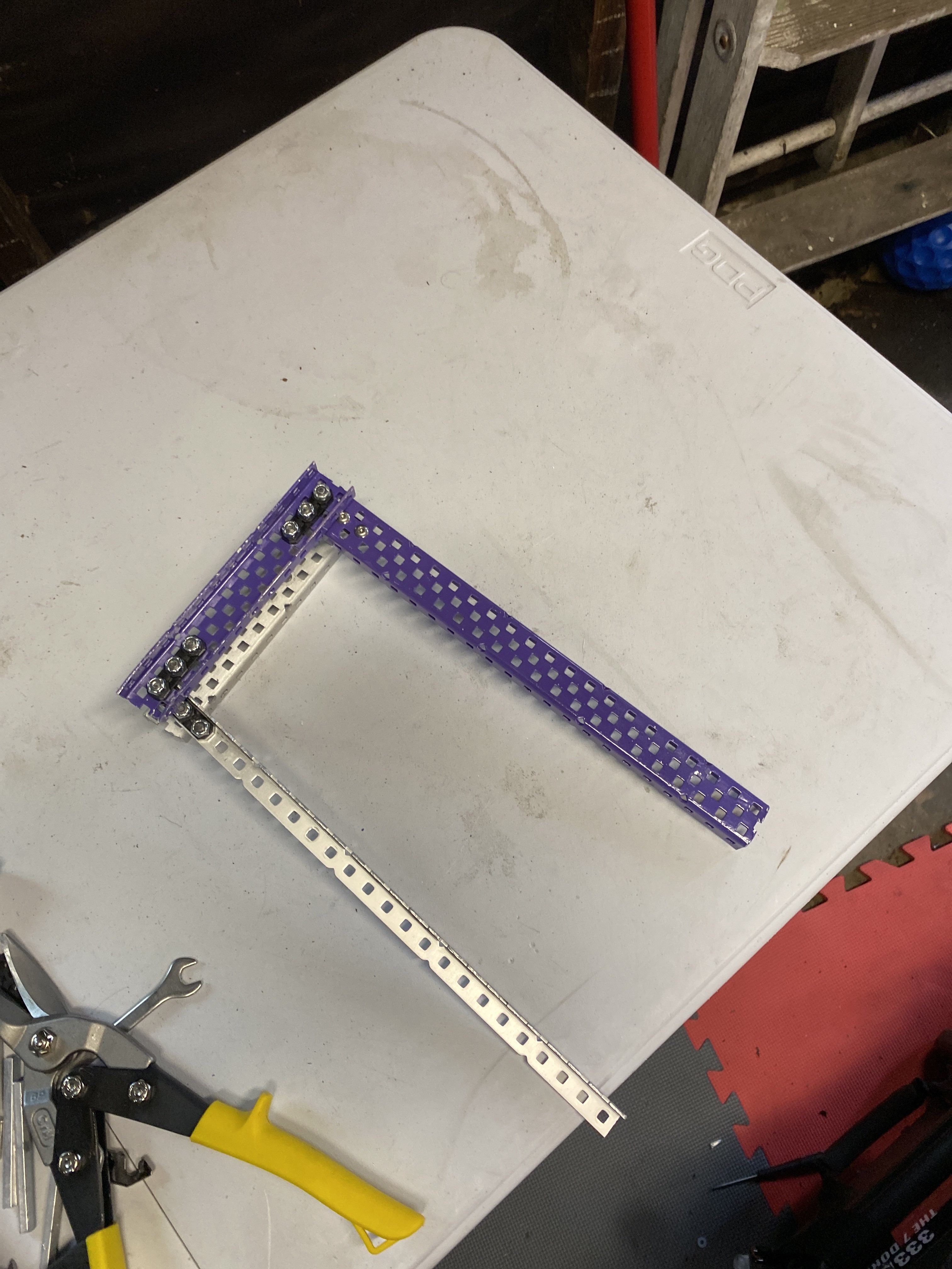
- The left mounting tower for the lift:

In building the lift, we had to make some minor changes to the CAD:
- We decided to build the mounting towers of the lift 1 hole shorter than the CAD, because we did not have enough metal of the right length. This change has little to no effect on functionality, because the bottom bar of the four bar can remain in the same place, so the mounting of the intakes can remain unchanged.
- We needed to change the spacing of the lower horizontal bar on the lift because we forgot to account for the screw heads. This has no effect on functionality, as the initial spacing was arbitrary.
- We were planning on using a screw joint to mount the primary intake roller, but the old sprockets we have do not take inserts, which means we cannot change the square inserts to round inserts, which we would need to do for a screw joint. To account for this, decided to add a bearing to the bottom of the half-cut c-channel the intake rollers are going to be attached to so we can use a shaft joint instead of a screw. This will likely add a small amount of friction and make the roller a little bit less stable, but not enough to significantly affect functionality.
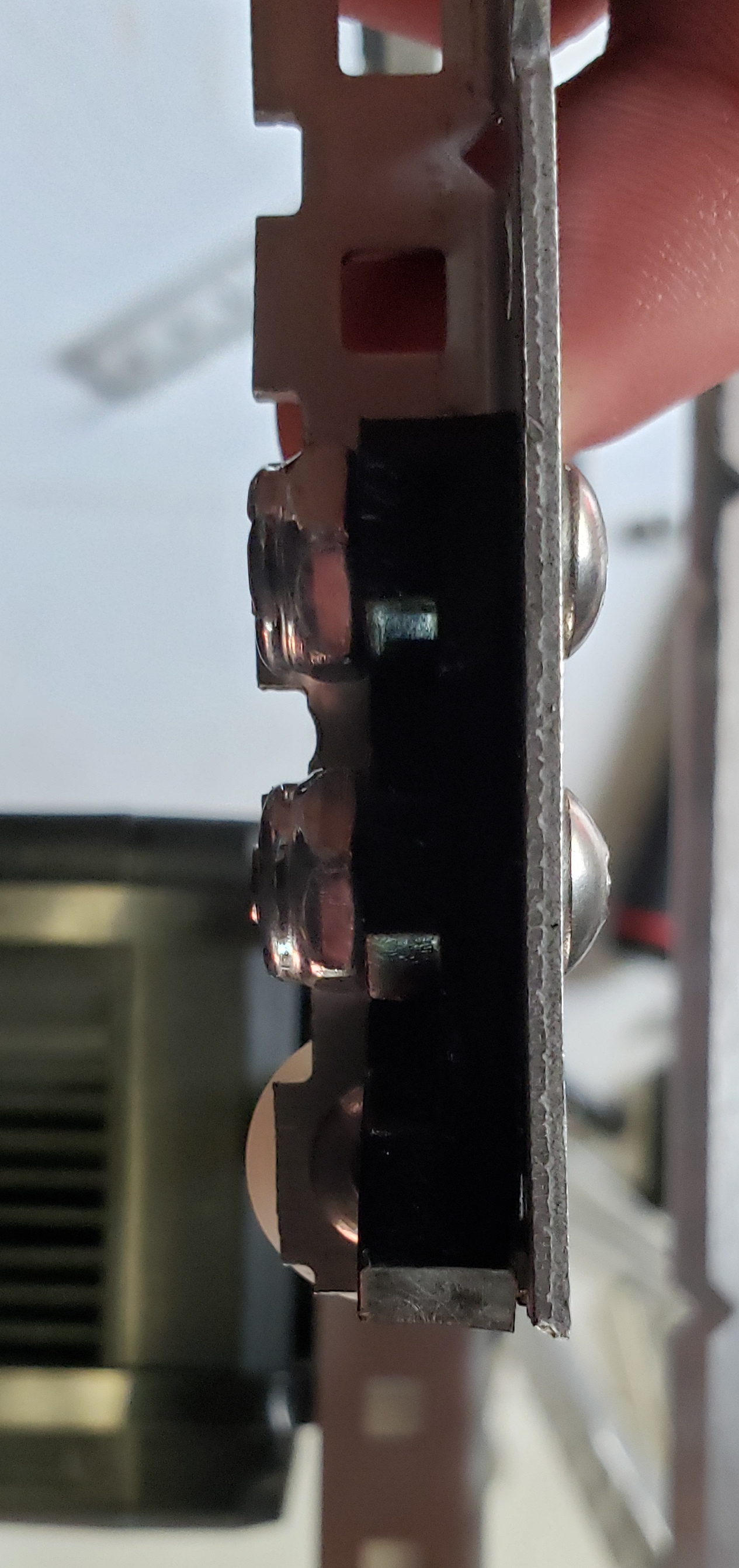
- We made the half-cut c-channel that the intake rollers are going to be attached to 1 hole longer so that the top bearing does not bend up over the shaft hole creating more friction, as shown on the bearing’s bottom hole in the image below. We cannot do this for the bottom bearing, because the shaft the roller goes through needs to be as low as possible.
 The 7 Dorks
the7dorks333A@gmail.com
The 7 Dorks
the7dorks333A@gmail.com